Servo controller part 2 - Theory
After reading posts on Pololu and l’Hexapod I decided the control theory of l’Hexapod seems like a better fit. He seems to have a greater control over the servo timing and pulse train. I’m assuming this control comes at a price, a more complex implementation.
For starters the, the amount of control I would like can only be achieved by ussing Assembly rather than C. Assembly allows me to create smaller and faster code. There is just one problem. The last time I actually did something with Assembly is over 20 years ago and even then it was just the basics.
The Theory
The PWM period is 20ms. The max duty cycle however seems to be between 2.1 and 2.5ms. That means that for at least 17.5ms the controller would do nothing. So we can break up the 20ms period in smaller chunks. 2.5ms each would mean we could control
20 / 2.5 = 8 servos.
Add Multiplexers to the hardware and we could get up to 64. With my assembly programming skills however I don really think this is feasible… at least not yet.
Lets paint a picture.
In the previous post. I showed this.
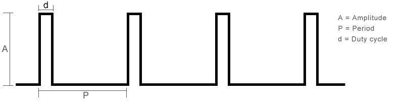
The PWM pulse train used to control servos. This image however shows nothing about timing, so here is another one.
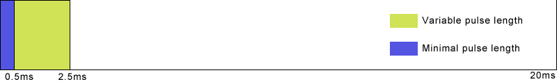
The image shows the diagram of a single 20ms cycle. All pulses start at the beginning of the cycle. I stated before that the pulse width determines the position of the servo. Exactly what pulse length correlates to which position seems to differ between servo types. In general though the left extreme position is no less than 0.5ms while the right extreme position is no more thatn 2.5ms. Please keep in mind that this is just from what I read at various sites on-line.
Anyway, looking at the diagram, one can’t help but notice the huge amount of idle time there is between 2.5ms and 20ms. This is where the breaking up comes in to play. Assuming the max pwm duty cycle is 2.5ms breaking it up in blocks of 2.5 will leave very little time to do anything else. so I decided to break the cycle up into four parts.
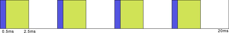
This way we make better use of the idle time and we can generate four pulses each cycle, using multiplexers that adds up to 32 servos. That seems like enough to control a hexapod mobile robot. Each cycle is identical.
So lets zoom in on the 5ms each of our cycles will be.
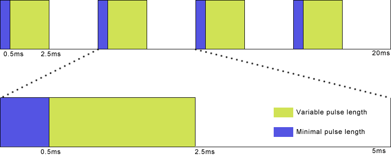
This image shows three distinct “periods” in every 5ms cycle. The period where all pins are high, a period where pins can be switched back to low and a 2.5ms period where all pins are low.
Of these three distinct periods the only one that can be constantly busy generating servo pulses is the yellow “Variable pulse length” period. It spans a maximum of 2ms. This leaves 3ms for activities such as calculating the pulses, determining when each pulse should end and handle communication.
Knowing when we have processing time available allows us to create a global sequence of events.
- Start pulses for the group (set pins to high)
- Handle communication
- End pulses fors the group (set pins to low)
- Handle communication
- Calculate Ending times for next cycles pulses
This of course is an overly simplified sequence of events. I have not yet figured out how it will look exactly.
For now I’m reading up on assembly programming and checking out interrupts and timing. That should provide me with enough information to create a sequence in much greater detail.
As always if you think something in here is wrong please let me know, thanks.